Jie Dong, Wenke Sun (2017). Internal co-seismic deformation and curvature effect based on an analytical approach. Earthq Sci 30(1): 47-56. DOI: 10.1007/s11589-017-0176-5
Citation:
Jie Dong, Wenke Sun (2017). Internal co-seismic deformation and curvature effect based on an analytical approach. Earthq Sci 30(1): 47-56. DOI: 10.1007/s11589-017-0176-5
Jie Dong, Wenke Sun (2017). Internal co-seismic deformation and curvature effect based on an analytical approach. Earthq Sci 30(1): 47-56. DOI: 10.1007/s11589-017-0176-5
Citation:
Jie Dong, Wenke Sun (2017). Internal co-seismic deformation and curvature effect based on an analytical approach. Earthq Sci 30(1): 47-56. DOI: 10.1007/s11589-017-0176-5
In this study, we present a new method to compute internal co-seismic deformations of a homogeneous sphere, based on our previous approach (Dong et al. 2016). In practical numerical computations, we consider a strike-slip point source as an example, and compute the vertical co-seismic displacement on different internal spherical surfaces (including the Earth surface). Numerical results show that the internal co-seismic deformations are generally larger than that on the Earth surface; especially, the maximum co-seismic displacement appears around the seismic source. The co-seismic displacements are opposite in sign for the areas over and beneath the position of the seismic source. The results also indicate that the curvature effect of the internal deformation is pretty large, and larger than that on the Earth surface. The results indicate that the dislocation theory for a sphere is necessary in computing internal co-seismic deformations.
Various dislocation theories have been developed for different geometrical Earth models, such as half-space media (Okada 1985; Okubo 1992), homogeneous sphere (Sun and Okubo 1993), or inhomogeneous sphere (Sun and Okubo 1993). The theory for a spherical Earth model is considered better than that for a half-space model, because the former takes the Earth curvature into account. However, due to the mathematical simplicity, the dislocation theory for a half-space model is still widely applied.
As modern geodetic technique developed, such as GPS and gravity missions, global co-seismic deformation could be detected. In this case, a more precise dislocation theory is actually necessary. We must be sure it is safe to apply a theory for a simple half-space Earth model in computing co-seismic deformation, especially for a far-field even a global scale deformation. Okubo et al. (2002) found the far-field displacement should be analyzed in the framework of spherical Earth theory by comparing the results for an elastic homogeneous half-space model and a radially stratified elastic Earth. For this purpose, some researchers made efficient studies to try to understand how large the effects of the curvature and layered structure are. So far, almost all the investigations are made for the deformation on the surface of the Earth, since the geodetic observation, such as GPS and gravity measurements, is usually performed on the Earth surface. Pollitz (1996) presented a method to illustrate the effects of Earth's sphericity and layering on the calculated deformation field, whose results showed the curvature effect is generally < 2% within 100 km of the point source depth. Sun and Okubo (2002) found that both the layering and curvature effects on the co-seismic surface deformation are very large. The layered structure effect reaches a discrepancy of more than 25%. Fu et al. (2010) studied the total effects of curvature and radial heterogeneity in the case of the 2008 Wenchuan earthquake and the 2004 Sumatra earthquake. Wang et al. (2010) found the total effects of the curvature and layer structures are large, without separating the two effects. Recently, Dong et al.(2014, 2016) systematically studied the effects of Earth's layered structure, gravity and curvature on co-seismic deformation. Their results show that those effects are very larger and cannot be neglected.
Notice again that all above studies were performed on the Earth surface. There are less study referring to the internal deformation, including the internal co-seismic deformation and the curvature effect. Although Okada (1992) presented a set of expressions of the internal deformation based on a homogeneous elastic half-space mode, the study about the internal deformation is still basically in the stage of theoretical discussion. Computing the internal co-seismic deformation can enhance our understanding of the stress status, mass redistribution, seismic mechanism, and so on. Recently, Takagi and Okubo (2017) presented a new method of computing internal displacement, stress, strain, and gravitational changes caused by a point dislocation in a spherical Earth model. However, in their method the asymptotic solutions of the radial functions are introduced. Actually, for a homogeneous sphere, it can be proved that the asymptotic solutions are not necessary; a more accurate and straightforward approach can be applied.
Therefore, in this study, we present a set of formulas to compute the internal deformation for the homogeneous spherical model, based on our previous study (Dong et al. 2016). Then we compare the internal co-seismic deformation computed by the new formula, and the corresponding deformation calculated by applying Okada's (1992) formulas, to investigate the curvature effect of the internal co-seismic deformation.
2.
Expressions of internal co-seismic deformations for a homogeneous sphere
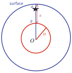
Conventionally, researchers study the surface co-seismic deformation (the blue sphere in Fig. 1) for a homogeneous sphere or an inhomogeneous sphere. In this section, we try to derive expressions to calculate internal deformations for a specified inner surface (such as the red sphere in Fig. 1). Although Okada (1992) presented analytical formulas for computing the internal deformation based on a homogeneous elastic half-space model, it is impossible to apply these formulas in the case of a sphere since the Earth's spherical curvature is neglected. Here, we derive the expressions of internal co-seismic deformations for a homogeneous sphere in spherical coordinates (r, θ, φ), where r is the geocentric distance, and (θ, φ) express the co-latitude and longitude, respectively, based on the approach of Dong et al. (2016).
Figure
1.
Sketch showing the positions of Earth (blue one) and the internal layer sphere (red one). R is the radius of the Earth, ds is the source depth, h is the internal layer depth under the surface, and H is the radius of the internal sphere
Since we consider a homogeneous sphere without gravity, the co-seismic displacement (u), and stress (τ) excited by a unit point source (f) at a location (r0, θ0, φ0) satisfies the equations of equilibrium and stress-strain relation (Alterman et al. 1959; Takeuchi and Saito 1972):
(1)
(2)
where I is the unit tensor, superscript T stands for transpose, and μ and λ are the Lame constants of the Earth.
Generally, any function can be expressed as spherical harmonics on a unit sphere. To solve Eqs. (1) and (2), the co-seismic displacement u(r, θ, φ) and stress τ(r, θ, φ) can be expressed as:
(3)
(4)
where er(r, θ, φ) is the radial unit vector, and τ·er(r, θ, φ) represents the radial component of the stress. Rnm(θ, φ), Snm(θ, φ), and Tnm(θ, φ) are conventional spherical harmonic functions,
(5)
Ynm(θ, φ), Yn-|m|(θ, φ) are functions of the associated Legendre's functions Pn (cos θ). (er, eθ, eφ) is the base vectors in spherical coordinate for radial, co-latitude and longitude directions, respectively. The superscript t stands for the toroidal deformation, which is parallel to the spherical surface. For the spheroidal deformation, y1 and y3 are radial and horizontal components of displacement; y2 and y4 are radial and horizontal components of stress, while y1t and y2t are horizontal displacement and stress of toroidal deformation, respectively. Similarly, the point force f can be expressed as spherical harmonics, and details are omitted here but can refer to Sun et al. (2009) or Dong et al. (2016).
Substituting the formulae (3)-(4) into (1) and (2), and neglecting the gravity effect (g = 0), we obtain four ordinary spheroidal differential Eq. (6) and two toroidal Eq. (7) as:
(6)
(7)
The general solution (X) of Eqs. (6) and (7) can be analytically obtained according to Love (1911). Although Love (1911) studied this problem, it is difficult to find a suitable solution of X from his publication; therefore, we derive the expressions of X in this study. Omitting the tedious mathematical work, we present four sets of fundamental spheroidal solutions yji(i, j = 1, 2, 3, 4) and two sets of toroidal solutions yjit(i, j = 1, 2).
The spheroidal solutions of the homogeneous Eq. (6), including two sets of regular solutions and two sets of irregular solutions, can be obtained analytically:
(8)
Similarly, the toroidal solutions (one regular solution and one irregular solution) are:
(9)
Then the general solution (X) can be expressed by a combination of the fundamental spheroidal solutions as
(10)
where βi are unknown constants. To determine the solution on the Earth surface, we introduce the boundary conditions,
Thus, we may obtain the following equations for the spheroidal solution. Here we take the vertical strike-slip source as an example. The strike-slip source is formed in shear force, with a relative movement across the strike of the fault:
(14)
where R is the radius of the Earth, and rs = (R-r0)/R denotes the normalized radius distance of the source. After solving Eq. (14), βi can be determined analytically, but the tedious calculations are not presented. Then, we can obtain the radial and horizontal components of displacement on the surface, and even inside the Earth.
Similarly, for the toroidal solution, we have:
(15)
The constants βi can be obtained in an analytical form as
(16)
Then we obtain the toroidal solution as
(17)
Similarly, we can obtain the solutions for other sources. Finally, we may compute co-seismic displacement u(r, θ, φ) by harmonics summation.
According to the above approach, we may easily derive the corresponding explicit expressions of internal deformations, by applying the four sets of fundamental spherical solutions (y) and two sets of toroidal solutions for a homogeneous Earth model. In order to derive expressions of the internal co-seismic deformations for any layer (h) inside the Earth, we should consider two conditions:
Case I When h < ds, i.e., the internal surface to be computed is over the seismic source, located between the Earth surface and the seismic source, and we get the y-variables by solving the following equations
(18)
Case Ⅱ when h > ds, i.e., the internal surface to be computed is beneath the seismic source, located between the seismic source and the mantle-core boundary, and we get the y-variables by solving the following equations
(19)
After deriving all these y-symbols based on the above mathematical processing, we may finally obtain the expressions of internal co-seismic displacement Green functions as
(20)
Note that although these formulas in Eq. (20) are given by spherical harmonic functions, they are still analytical solutions. These summations in Eq. (20) can be evaluated analytically using the mathematical skill as used in Sun et al. (2009). It means that we can compute the co-seismic deformations for any layer inside the Earth. In a practical computation, in the above scheme, the inputs we need are the source depth ds, internal surface depth h, and radius R.
3.
Internal co-seismic deformations of a homogeneous sphere
In order to display the internal deformations, we assume a strike-slip point source to locate at north pole (Sun and Okubo 1993). Then we consider two source depths at 30 and 637 km, respectively. The 30-km source represents a shallow event, and the 637-km (10% of the Earth radius) source stands for a deep event, so that we can observe the property of the inner deformation and the curvature effect for different source depth.
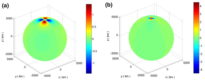
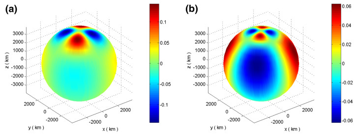
Applying the above computing scheme, we calculate co-seismic displacements on two internal spheres caused by the two sources, with depth of h = 1000 km and h = 2500 km. Figure 2 shows the vertical co-seismic displacements on an internal sphere with depth of h = 1000 km, caused by the two sources, while Fig. 3 gives the same results as Fig. 2 but for an internal sphere of h = 2500 km. Both Figs. 2 and 3 show that the co-seismic deformation behaves in a quadrant pattern, similar to the deformation on the Earth surface. Since the Earth's surface in the quadrants 1 and 3 sink down, and the other two quadrants rise (further discussions on the distribution of the surface deformation refer to the Figs. 4, 5 below); while the deformation at the two internal spheres (h = 1000 km and h = 2500 km) shown in Figs. 2 and 3 indicates that the deformation in the quadrants 1 and 3 rise, and the quadrants 2 and 4 sink down. The reason for this opposite deformation between the Earth surface and the inner surface is due to the position of the inner surface. Generally, we found that if the internal surface is located beneath the source, the deformation appears opposite in sign with that over the source (including the earth surface).
Figure
2.
Vertical displacement on the internal sphere h = 1000 km caused by the strike-slip point source (UdS/R2= 1) at depths of 30 km (a) and 637 km (b), the vertical displacement is dimensionless
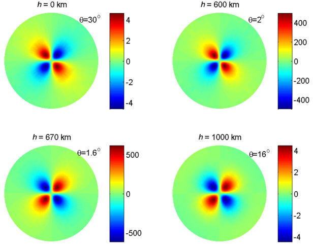
Figure
4.
Vertical co-seismic displacements on different internal spheres (h is the depth under the surface) caused by the strike-slip point source (UdS/R2= 1) at a source depth of 30 km, the vertical displacement is dimensionless
Comparing Fig. 2a, b shows that the amplitude of the vertical displacement caused by the source at radius of 637 km is larger than that at radius of 30 km, because the source at ds = 637 km is nearer to the internal surface of h = 1000 km. In addition, the magnitude of the vertical displacements for both depths decays quickly as the epicentral distance (θ) increases, meaning that the local co-seismic deformation dominates.
From Fig. 3, we see that the amplitude of the co-seismic displacements on the internal sphere of h = 2500 km is smaller than that on the sphere of h = 1000 km. This phenomenon is normal, because the former is farther from seismic source and the deformation decays with distance. In addition, the deformation on sphere of h = 2500 km appears wide distribution covering a more large area, because the farther the distance apart from the seismic source, the weaker the co-seismic deformations. It means that the high frequency components of the deformation become weaker and weaker, while the low frequency components become dominating.
To observe the property of the co-seismic displacements changing for different depth, we compute and plot co-seismic vertical displacements on several internal spheres with different depths (0, 20, 60 and 1000 km) and different epicentral distance θ. Results are plotted in Fig. 4 for a seismic source depth of 30 km, and in Fig. 5 for a source depth of 637 km. In Fig. 4, when h = 0 km (on the surface of the Earth), we find that the larger displacements appear within θ= 1°, almost the same as that of the homogeneous sphere's numerical solutions of Sun et al. (2009). When h = 20 km, the larger displacements appear within θ= 0.4° and show largest deformation in magnitude among the four depths, more concentrate to the epicenter, because the deformation on the internal sphere of h = 20 km is nearer to the source of 30 km than the Earth surface (h = 0 km). When h = 60 km, we find that the co-seismic displacement is much smaller than that on the Earth surface, even though the distances between the seismic source (h = 30 km) and the two spheres (h = 0 km and h = 60 km) are the same. This phenomenon is understandable, because the co-seismic deformation depends on the geocentric distance, and the distances from the Earth's center to the Earth surface and depth of 60 km are different. Finally when h = 1000 km, the larger co-seismic displacement appears in wider area, covering large epicentral distance. On the other hand, the magnitude of the displacement is much smaller than that on other spheres, because this sphere (h = 1000 km) is very far from the source and the deformation decays quickly.
In addition, we find that the coverage (epicentral distance) of the largest deformation is proportional to the distance of (|h - ds|). That is, the epicentral distance for the large deformation becomes larger as the internal sphere farther from the source. Furthermore, we find that, as pointed out above, the co-seismic displacements are opposite in sign for those areas over and beneath the seismic source. Generally, the displacement becomes large when the computing point is near the source, as shown in Figs. 4 and 5.
Comparing Figs. 4 and 5 shows that the internal deformation obviously changes for different source depth. The vertical displacements on the Earth surface become much smaller when the source is located in depth of 637 km, while the deformation on sphere of h = 1000 km becomes larger due to the relatively near source. Note that all properties shown in Fig. 4 also apply to Fig. 5.
4.
Curvature effect in computing internal co-seismic deformations
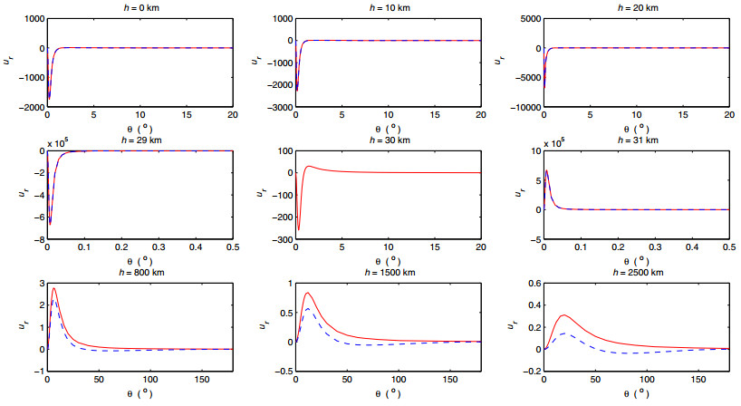
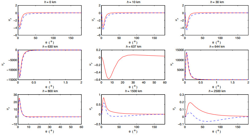
In this section, we investigate the curvature effect for internal co-seismic deformation based on the above approach. For this purpose, we calculate internal vertical co-seismic displacements for different depths by using the above approach and the theory of Okada (1992). In computation, we consider two strike-slip seismic sources at depths of 30 and 637 km, respectively. Similarly, the point source is normalized by factor of UdS/R2 = 1. Then we compute the vertical displacements for different depths (or internal spheres) and plot them in Figs. 6 and 7, for the two sources, respectively. A comparison of vertical co-seismic displacements on different internal spheres (h) computed by half-space model (red line) and spherical model (blue dashed line) is clearly shown in the figures. The difference between the results represents the curvature effect of the internal deformation.
Figure
6.
Comparison of vertical co-seismic displacements on different internal spheres (h) computed by half-space model (red line) and spherical model (blue dashed line) caused by the strike-slip point source (UdS/R2 = 1) at a source depth of 30 km, the vertical displacement is dimensionless
Figure 6 shows that the difference (curvature effect) between the two theories on Earth surface and shallow areas over the source is not obvious and difficult to be identified since both curves overlap, although the numerical result shows the curvature effect is about 1.2% on the surface. However, the curvature effect becomes larger and larger when the depth of the internal sphere goes deeper and deeper. However, when the source locates deep as shown in Fig. 7 for depth of 637 km, the curvature effect becomes larger, even we can identify them directly. It means that the curvature effect becomes larger for deep seismic events.
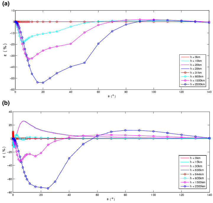
To evaluate the curvature effect in quantity, we represent the curvature effect in form of a relative error defined as
(21)
where u(s) is the displacement computed for a spherical model, u(h) is that computed for a half-space model (Okada 1992), while the term |u(h)|max stands for the maximum value of the co-seismic deformation. Then the curvature effects in Figs. 6 and 7 can be represented in Fig. 8a, b. Figure 8 shows that the curvature effect on the Earth surface is small, which is about 1.2%, in agreement with the conclusion of Dong et al. (2016). It also shows that the curvature effect (ε) becomes larger as the distance between the internal sphere and the source goes larger. Figure 8 also shows a proportional relation between the curvature effect and the source depth, i.e., ε∝|h-ds|. This relation should be further proved in theory or more numerical work.
Figure
8.
Curvature effects on different inner spheres caused by the strike-slip point source (UdS/R2 = 1) at depths of 30 km (a) and 637 km (b). The Subplot a shows that the curvature effects for those internal spheres are 1.2%, 1.1%, 0.7%, 0.4%, 0.4%, 18%, 33%, and 54%, respectively; b shows that the corresponding curvature effects are 26.1%, 26%, 25.8%, 11.6%, 10.4%, 12.2%, 34%, and 75%, respectively
In this study, we present expressions for computing the internal deformation of a homogeneous sphere, based on our previous approach (Dong et al. 2016). These expressions are given in form of analytical solutions, similar to that of Okada (1992), which is given for a homogeneous half-space model. In practical numerical computations, we consider a strike-slip point source as an example, and compute the vertical co-seismic displacement on different internal spherical surfaces (including the Earth surface).
Numerical results of the internal deformations show that the internal co-seismic deformations are generally larger than that on the Earth surface; especially, the maximum co-seismic displacement appears around the seismic source. For the point source at depth of 30 km, the displacement magnitude reaches about 105(normalized by factor of UdS/R2 = 1) near the source, while the displacement amplitude in other places decreases quickly as the distance apart from the source increases. The results also show that the displacements are opposite in sign for the areas over and beneath the position of the seismic source. The results of the study also indicate that the curvature effect of the internal deformation is pretty large. Our previous study (Dong et al. 2016) on the Earth surface showed that the curvature effect is generally < 5% for point source with depth less than 100 km. The current study shows that the curvature effect of internal deformation becomes larger comparing to the surface, e.g., the curvature effect on the CMB (core-mantle boundary) spherical surface can reach 100%. The above results indicate that the dislocation theory for a sphere is necessary in computing internal co-seismic deformations, comparing to the theory for a half-space media (Okada 1992).
Note that since the numerical computations are made for only the strike-slip source and the vertical co-seismic displacement in the study, the corresponding conclusions are actually limited. Because the co-seismic deformations include different geophysical phenomena, such as displacement, strain, potential (geoid) and gravity changes, the corresponding deformation property and pattern are different. The displacement is a vector, including two components, vertical displacement and horizontal displacement, and its spatial distribution pattern and magnitude are different. In addition, all these co-seismic deformations appear different spatial distribution property, depending on source types, source depth. Therefore, the numerical computation and discussion and conclusions are considered as a case study. For different source types and different co-seismic deformations, there may be somehow changeable or adjustable conclusions, maybe slightly. However, the method and conclusions in this study are still important in enhancing our understanding of the property of the internal deformation and curvature effect.
The method presented in this study can be used to compute Green's functions of the internal co-seismic deformation, including all types of physical variables, such as displacement, strain, tilt, and so on. Then we may apply the Green's functions to compute co-seismic deformations at any source depth by arbitrary source types, though simple numerical integrations over limited fault plane. These practical applications remain in our future work.
Acknowledgements
We thank two anonymous reviewers for their careful reading in the previous version of the paper and for their helpful comments. This research was supported financially by the National Natural Science Foundation of China (Nos. 41331066, 41604067 and 41474059), China Postdoctoral Science Foundation Funded Project (No. 119103S268), CAS Key Study Program QYZDY-SSW-SYS003 and the CAS/CAFEA International Partnership Program for Creative Research Teams (No. KZZD-EW-TZ-19).
Open Access
This article is distributed under the terms of the Creative Commons Attribution 4.0 International License (http://creativecommons.org/licenses/by/4.0/), which permits unrestricted use, distribution, and reproduction in any medium, provided you give appropriate credit to the original author(s) and the source, provide a link to the Creative Commons license, and indicate if changes were made.
Alterman Z, Jarosch H, Pekris CL (1959) Oscillation of the Earth. Proc R Soc. Lond A252:80-95 doi: 10.1098/rspa.1959.0138
Dong J, Sun W, Zhou X, Wang R (2014) Effects of Earth's layered structure, gravity and curvature on coseismic deformation. Geophys J Int 199:1442-1451 doi: 10.1093/gji/ggu342
Dong J, Sun W, Zhou X, Wang R (2016) An analytical approach to estimate curvature effect of coseismic deformations. Geophys J Int 206:1327-1339 doi: 10.1093/gji/ggw215
Fu G, Sun W, Fukuda Y, Gao S, Hasegava T(2010) Effects of Earth's curvature and radial heterogeneity in dislocation studies: case studies of the 2008 Wenchuan earthquake and the 2004 Sumatra earthquake. Earthq Sci 23:301-308 doi: 10.1007/s11589-010-0727-5
Love AEH (1911) Some problem of geodynamics. Cambridge University Press, Cambridge, pp 89-104
Okubo S (1992) Potential and gravity changes due to shear and tensile faults. J Geophys Res 97:7137-7144 doi: 10.1029/92JB00178
Okubo S, Sun W, Yoshino T, Kondo T, Amagai J, Kiuchi H, Koyama Y, Ichikawa R, Sekido M (2002) Far-field deformation due to volcanic activity and earthquake Swarm, Vistas for geodesy in the New Millennium. In: Adam J, Schwarz KP (eds) International Association of Geodesy Symposia, vol 125, pp 518-522
Pollitz FF (1996) Coseismic deformation from earthquake faulting in a layered spherical Earth. Geophys J Int 125:1-14 doi: 10.1111/gji.1996.125.issue-1
Sun W, Okubo S (1993) Surface potential and gravity changes due to internal dislocations in a spherical Earth, Ⅰ. Theory for a point dislocation. Geophys J Int 114(3):569-592 doi: 10.1111/gji.1993.114.issue-3
Sun W, Okubo S (2002) Effects of Earth's spherical curvature and radial heterogeneity in dislocation studies-for a point dislocation. Geophys Res Lett 29(12):1605. doi: 10.1029/2001GL014497
Sun W, Okubo S, Fu G, Araya A (2009) General formulations of global co-seismic deformations caused by an arbitrary dislocation in a spherically symmetric Earth model—applicable to deformed Earth surface and space-fixed point. Geophys J Int 177:817-833. doi: 10.1111/j.1365-246X.2009.04113.x
Takagi Y, Okubo S (2017) Internal deformation caused by a point dislocation in a uniform elastic sphere. Geophys J Int 208:973-991 doi: 10.1093/gji/ggw424
Wang W, Sun W, Jiang Zaisen (2010) Comparison of fault models of the 2008 Wenchuan earthquake (MS8.0) and spatial distributions of co-seismic deformations. Tectonophysics 491:85-95 doi: 10.1016/j.tecto.2009.08.035
Liu, T., Fu, G., She, Y. et al. Post-seismic crustal internal deformation in a layered earth model. Geophysical Journal International, 2021, 226(3): 1584-1598.
DOI:10.1093/gji/ggab156
2.
Liu, T., Fu, G., She, Y. et al. Co-seismic internal deformations in a spherical layered earth model. Geophysical Journal International, 2020, 221(3): 1515-1531.
DOI:10.1093/gji/ggaa086
3.
Malesza, J., Miedzialowski, C., Ustinovichius, L. Analytical model tracing deformations in multistorey large timber panel building. Journal of Civil Engineering and Management, 2019, 25(1): 19-26.
DOI:10.3846/jcem.2019.7738

 DownLoad: